RADAR LOCATION ERRORS
In Unclassified Data In The Public Domain
The aerial maps provided show serious errors discovered in the latitude and longitude coordinate locations
of radars as documented in unclassified data in the public domain.
These radars consist of Airport Surveillance Radars (ASR), Secondary Surveillance Radars (SSR),
and Air Route Surveillance Radars (ARSR).
Having accurate radar location data is crucial for aircraft Collision Warning System (CWS) passive mode operation
during which the system listens to SSR interrogations and the replies from aircraft transponders.
Since the radar data is critical to flight safety, the data for each radar must be verified.
Street Views Of Radars
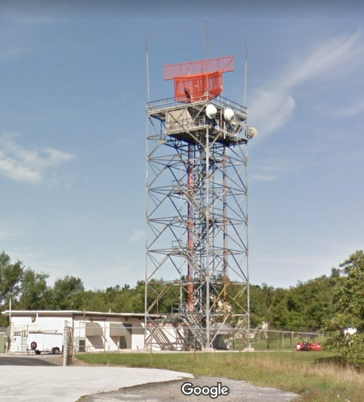
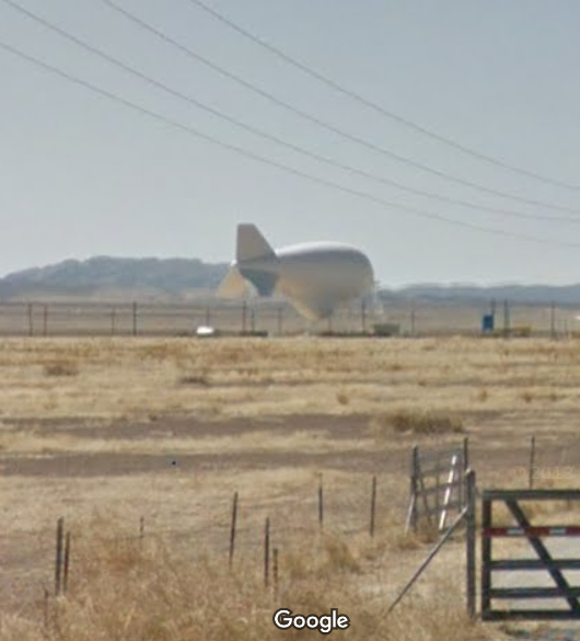
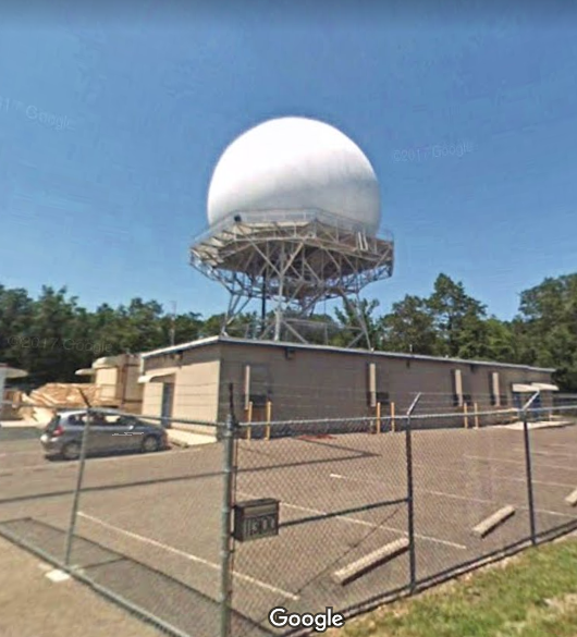
The Google Maps Street View photos below are of the Harrisburg ASR (left),
a Tethered Balloon with radar mounted to the underside (middle), and the Egg Harbor ARSR (right).
The SSR portion can be seen mounted on top of the ASR (left).
The Tethered Balloon radar and ARSR include an SSR but cannot be seen due to the radar radomes (protective cover).
NOTE: The set of buttons above each image allow you to Zoom In and Out of the image.
Zooming is most effectively performed by clicking on 'ZOOM IN' or 'ZOOM OUT' and then pressing the enter key repeatedly as desired.
Panning is most effectively performed by using the cursor keys.
|
|
|
ARSR photographs provided to The Air Defense Radar Museum may be seen at ARSR Photographs for The Air Defense Radar Museum.
Radar Location Measurements
A hand-held Global Positioning System (GPS) Receiver was used to determine the locations of the radars.
When it was not possible to take a GPS reading at the base of the radar, a Range Finder and Pocket Transit were
used to measure the range and bearing to the radar from an observation location to then calculate the
location of the radar.
For radars out of range from the Range Finder, the radar location is calculated from two observation
locations and bearings to the radar.
Note that these measurements were performed when GPS included a feature called Selective Availability (SA) that intentionally added random time varying errors to produce location errors of up to 100 meters. The purpose of SA was to deny an enemy the use of civilian GPS receivers for precision weapon guidance. SA was turned off on May 2, 2000.
Viewing And Using ESRI Arc GIS for Spherical Projection Map
The ESRI Arc GIS Spherical Projection map is provided at:
Radar Location Errors (Arc GIS).
Viewing And Using Google Maps for Mercator Projection Maps
The Google Maps message below, with "For development purposes only" appearing throughout the map, may be ignored:

Simply click on "OK" (possibly twice) and that message will disappear.
Zoom in and out of the Google Map by clicking on the "Zoom in" icon (+) and "Zoom out"
icon (-) located at the lower right corner of the map.
Expand the Google Map to fill the entire screen by clicking on the "Toggle fullscreen view"
icon ([ ]) located at the upper right corner of the map.
The Google Map "Tilt map" and "Rotate map 90 degrees" icons are available when zoomed closer in.
Pan in the Google Map by holding the mouse pointer down on the map and pulling the map in the desired direction.
Clicking on the map with the left button toggles the lines on and off.
Clicking on the map with the right button toggles the markers on and off.
With markers off, detailed analysis of the path is permitted and plotting is much swifter.
Viewing Images Of Google Maps
In images of Google Maps maps, the Google Maps icons are blackened out because clicking on an icon image will have no affect.
However, the set of buttons above each image allow you to Zoom In and Out of the image.
Zooming is most effectively performed by clicking on 'ZOOM IN' or 'ZOOM OUT' and then pressing the enter key repeatedly as desired.
Panning is most effectively performed by using the cursor keys.
Radar Location Maps
The maps provide an indication of the accuracy of GPS during SA and can reveal map alignment and distortion issues in which a radar will not appear precisely at the latitude/longitude coordinate location. Each marker on the maps points to a latitude/longitude location. The marker text color indicates one of the following with additional information provided when hovering the mouse pointer over that marker:
| COLOR | INDICATION | HOVER INFORMATION |
| WHITE | Public domain unclassified data radar location name where radar exists. Example: HOUSTON |
Name with possible substantial location error(s). Example: HOUSTON Error: 11.66nm |
| RED | Public domain unclassified data radar location name where no radar exists
as discovered when going there to take GPS reading. Example: PHILADELPHIA (2) |
Name with additional information. Example: PHILADELPHIA 2 Records: One of radar relocated to CA, other of Restoration Facility 23.5nm north |
| GREEN | GPS location at named radar or at observation location. Examples: WALLOPS ISLAND or OBSERVATION |
Name or range and bearing to radar. Examples: WALLOPS ISLAND NASA or Range: 0.309nm (625yd), Bearing: 285° (Magnetic) |
| YELLOW | Calculated location using GPS observation location and measured range and (or) bearing(s). Example: MARTINSBURG |
Named Calculated. Example: MARTINSBURG Calculated |
| MAGENTA | Calculated location using indicated Magnetic Variation. Examples: +MagVar W09.58° and -MagVar W09.58° |
Magnetic Variation adjusted bearing (with calculated magnetic variation). Example: Bearing: 294.58° (+MagVar W09.58°) and Bearing: 275.42° (-MagVar W09.58°) |
| BLUE | Survey plate at base of radar location name. Example: GULFPORT SURVEY PLATE |
Survey plate latitude, longitude. Example: GULFPORT SURVEY PLATE: N30° 24' 22.7", W089° 04' 54.8" |
Magnetic variation is the angle between magnetic north and true north.
A west magnetic variation indicates magnetic north is west (counter clockwise) of true north.
A true north bearing is calculated from a magnetic bearing by adding (clockwise)
a west magnetic variation to the magnetic bearing.
An east magnetic variation indicates magnetic north is east (clockwise) of true north.
A true north bearing is calculated from a magnetic bearing by subtracting (counter clockwise)
an east magnetic variation from the magnetic bearing.
The magnetic variations were calculated using the World Magnetic Model of 1990 (WMM-1990).
Note that the maps include both of the locations that result after adding and subtracting magnetic
variation to and from the magnetic bearings.
To see how the magnetic variation varies over the planet, as calculated using WMM-1990,
see Magnetic Variation.
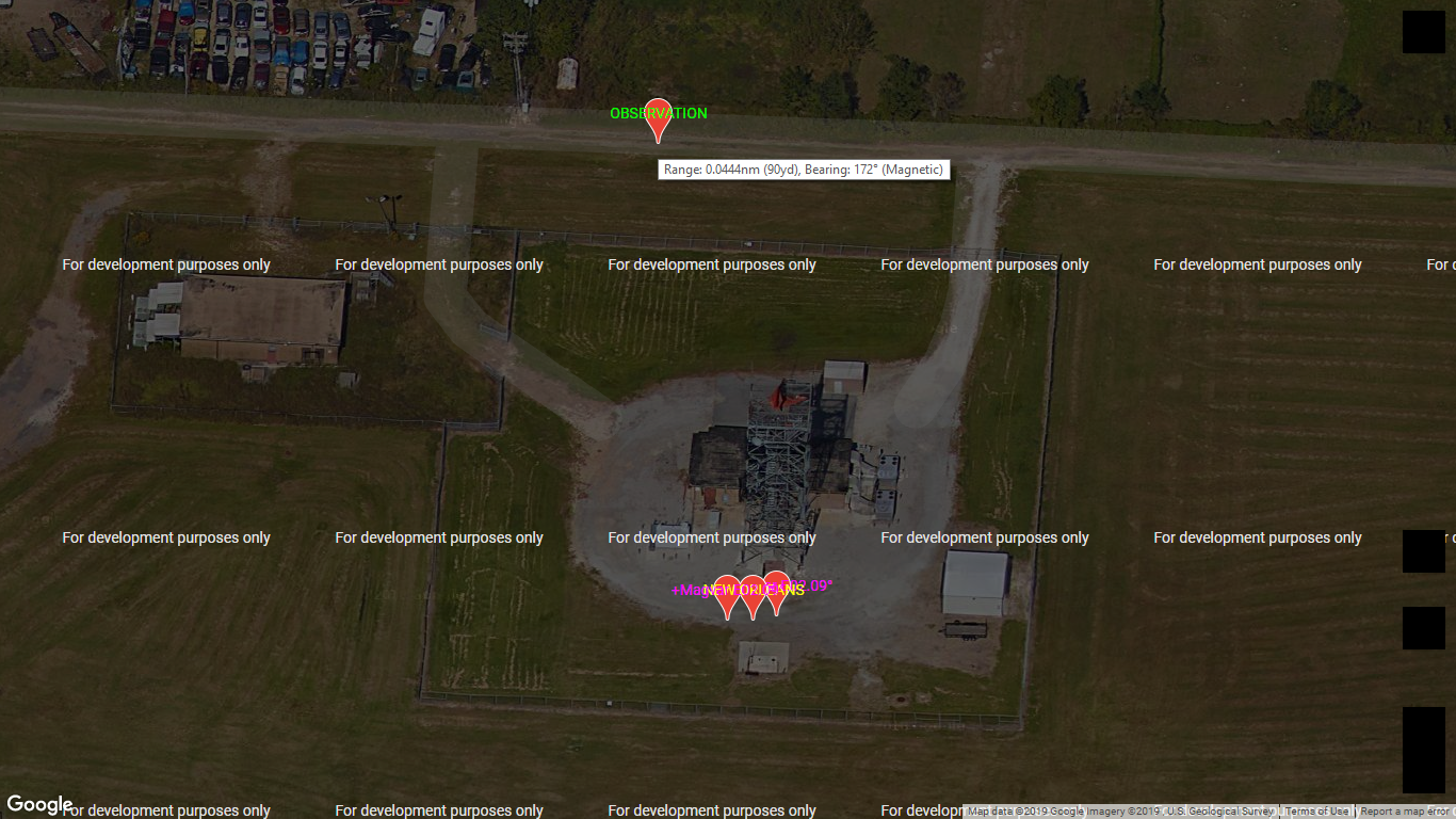
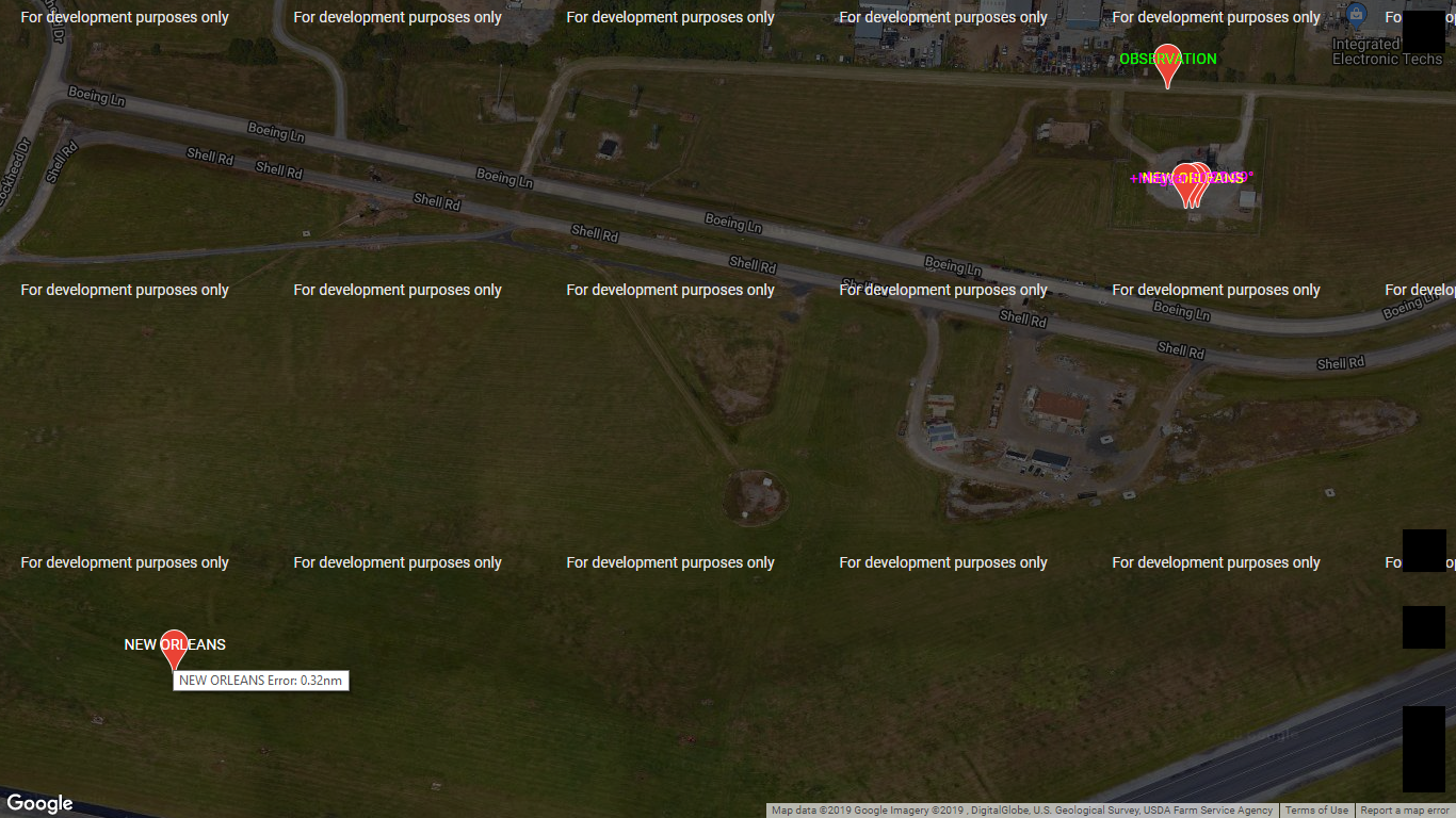
A tilted map example follows for the FAA NEW ORLEANS radar that can be seen with the 85' gray
tower and orange ASR/SSR.
That radar was observed from the GPS observation location and the range and bearing to that radar
was measured with the Range Finder and Pocket Transit.
The observation location marker text is "OBSERVATION" in green and hovering the mouse pointer over that marker
gives the range and bearing to that radar as "Range: 0.0444nm (90yd), Bearing: 172° (Magnetic)",
where "nm" is nautical miles and "yd" is yards.
The calculated location marker text is "NEW ORLEANS" in yellow and the calculated locations marker texts "MagVar E02.09°"
in magenta were calculated using the indicated magnetic variation added to and subtracted from magnetic bearing.
The zoomed out map image below shows that the unclassified public domain data location, with the marker text "NEW ORLEANS" in white (lower left in image below), has the radar located 0.32 nautical miles southwest of where the radar is actually located (upper right in image below) as shown above:
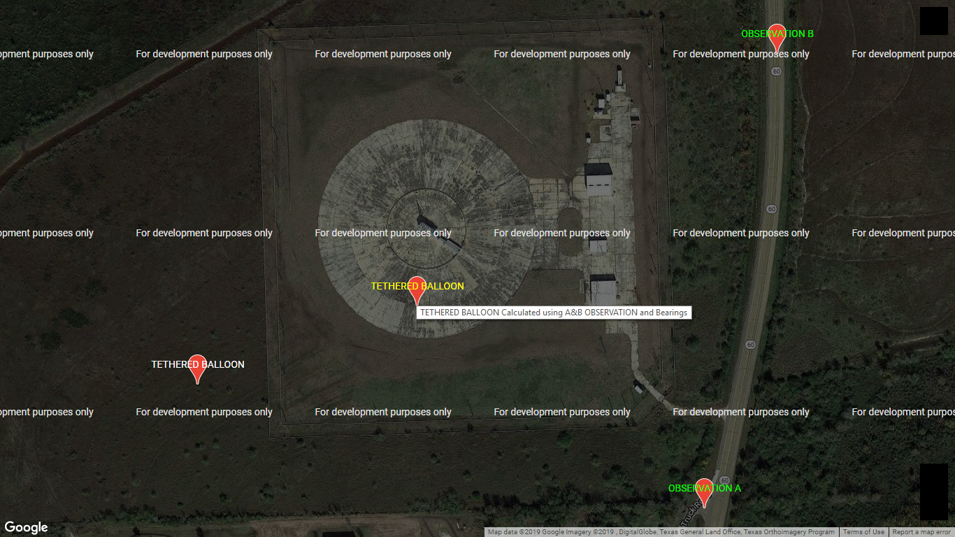
The example below shows a TETHERED BALLOON radar location calculated from the two observation locations and bearings to the radar. Note that because the range to the radar was within the 1,000 yard limitation of the Range Finder, only one observation location and the range and bearing to the radar is needed; however, this measurement was performed to show the results without using a Range Finder:
RADARS MEASURED
The following radars were measured with the location determined by using a GPS Receiver and, if required, a Range Finder and Pocket Transit:
RADARS WITHIN 120nm OF PATUXENT RIVERThe Google Maps API (Application Programming Interface) maps showing the radars with markers and text identifying the radar location as documented in the unclassified public domain data and the location as measured follow. A few examples of serious radar location errors discovered are shown in the images after each map. Radars thought to exist did not exist, radars existed that were not known to exist, and radar location errors of 23.5 nautical miles (nm) and over (e.g. relocated thousands of miles away) were discovered.
RADARS WITHIN 175nm OF WHITING FIELD
RADARS WITHIN 175nm OF CORPUS CHRISTI
RADARS WITHIN 120nm OF PATUXENT RIVER
The Google Maps API map below identifies the 38 radars measured within
the 120 nautical mile (nm) radius circle below that is centered on the Patuxent River radar.
A few examples of serious radar location errors discovered in the unclassified public domain data
are shown in the images after the map below:
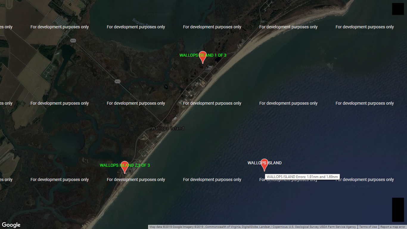
The image below shows that there is not one (1) radar at WALLOPS ISLAND, which the unclassified public domain data has located out in the Atlantic Ocean at the marker with white text, but actually three (3) radars that are located on land with green text and are located between 1.69 and 1.91 nautical miles from that data location:
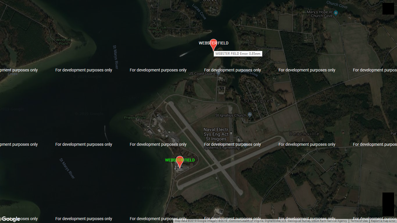
The image below shows the WEBSTER FIELD radar, which the unclassified public domain data has located out in the St. Mary's River with white text, located on land with green text 0.85 nautical miles from that data location:
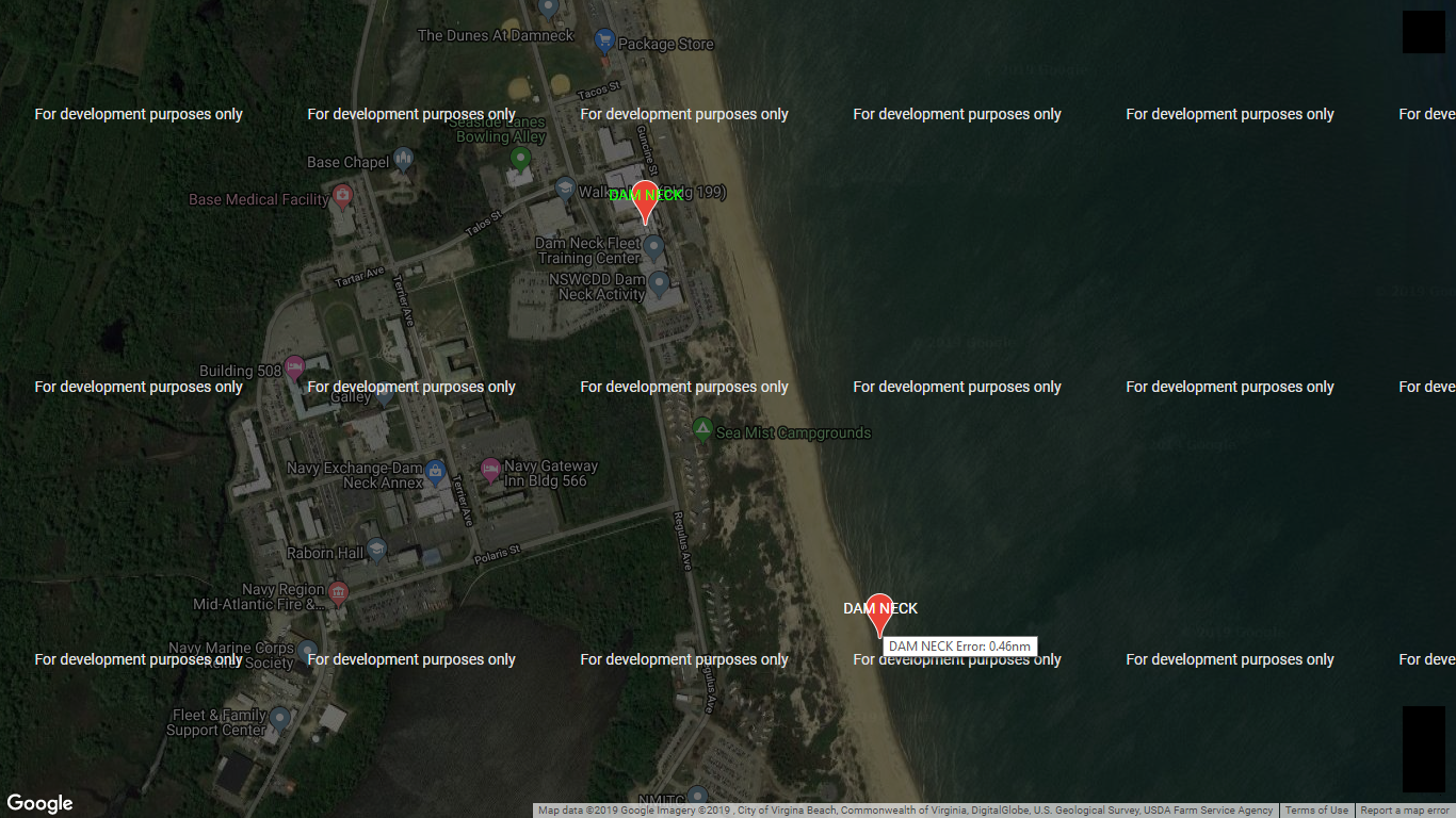
The image below shows the DAM NECK radar, which the unclassified public domain data has located out in the Atlantic Ocean with white text, located on land with green text 0.46 nautical miles from that data location:
RADARS WITHIN 175nm OF WHITING FIELD
The Google Maps API map below identifies the 44 radars measured within
the 175nm radius circle below that is centered on the Whiting Field radar.
A few examples of serious radar location errors discovered in the unclassified public domain data
are shown in the images after the map below:
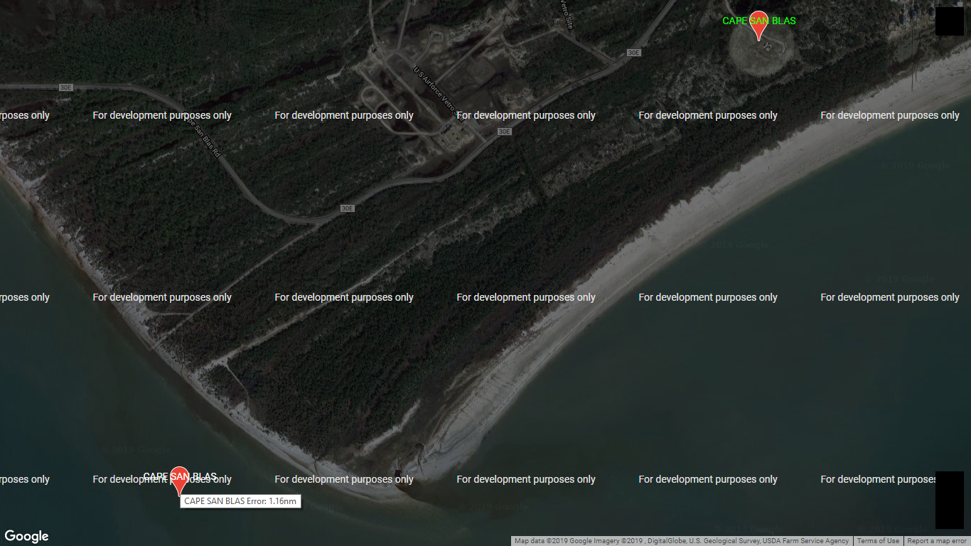
The image below shows the CAPE SAN BLAS radar, which the unclassified public domain data has located out in the Gulf Of Mexico with white text, located on land with green text 1.16 nautical miles from that data location:
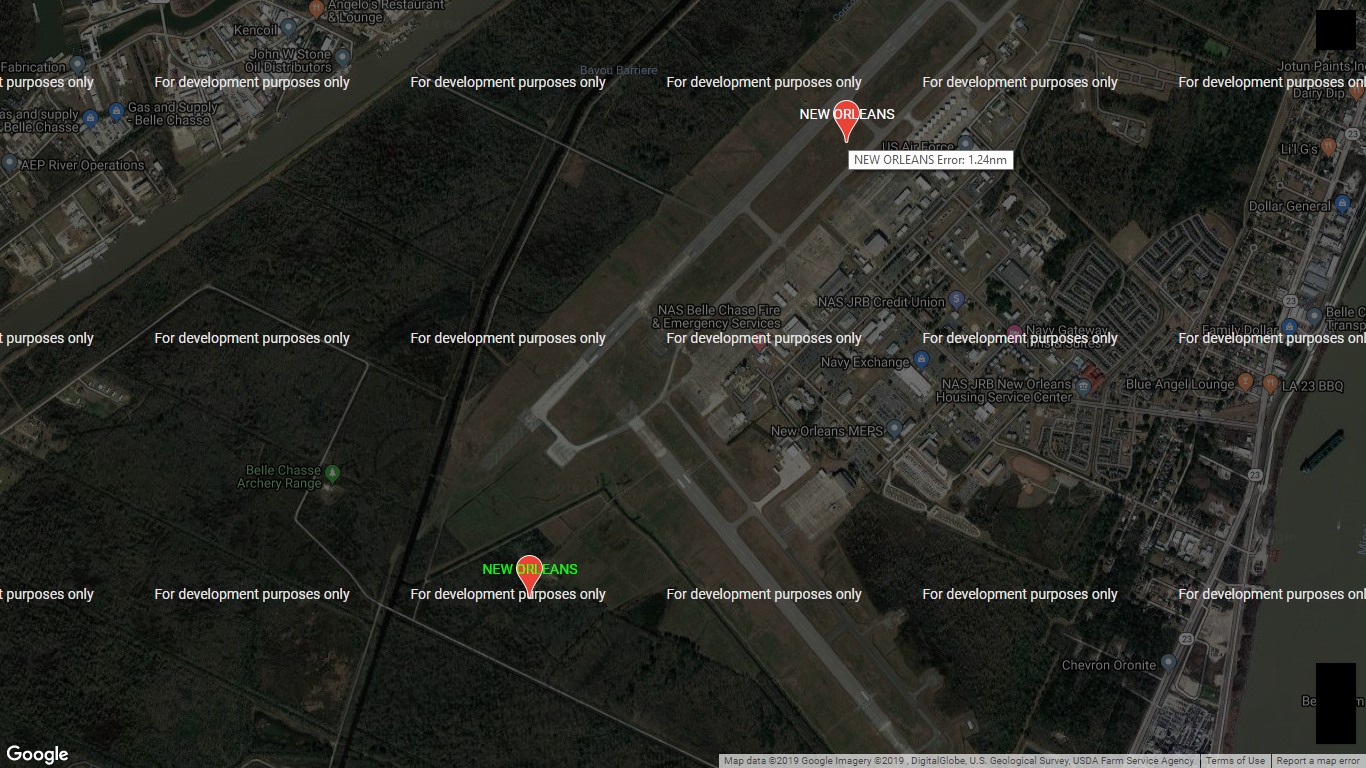
The image below shows the Navy NEW ORLEANS radar, which the unclassified public domain data has located at the marker with white text, located at the marker with green text 1.24 nautical miles from that data location:
RADARS WITHIN 175nm OF CORPUS CHRISTI
The Google Maps API map below identifies the 16 radars measured within
the 175nm radius circle below that is centered on the Corpus Christi radar.
A few examples of serious radar location errors discovered in the unclassified public domain data
are shown in the images after the map below:
The image below shows the HOUSTON radar, which the unclassified public domain data has located at the marker with white text, located at the marker with green text 11.66 nautical miles from that data location:
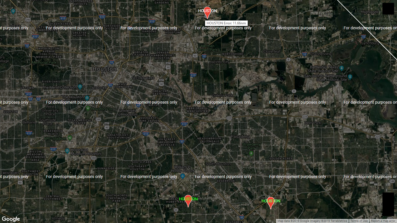
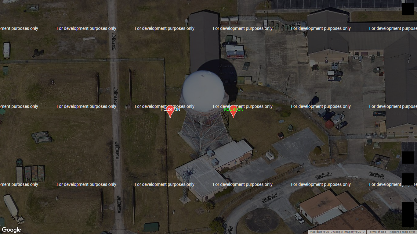
Note that the HOUSTON with green text southeast in the image above is associated with a different HOUSTON radar for which the unclassified public domain data is acceptable as shown in the zoomed in tilted map below that shows the GPS location is virtually identical to that data:
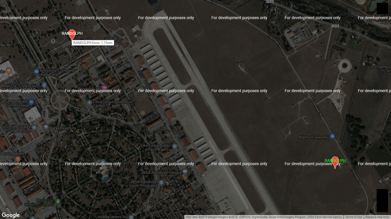
The image below shows the RANDOLPH radar, which the unclassified public domain data has located at the marker with white text, located at the marker with green text 1.15 nautical miles from that data location:

<>